Tutorial 2: Creating a Schematic and Running a Simulation
This tutorial will show you how to create a simple schematic and perform a transient analysis upon it. It is intended for beginner users.
This assumes you have SIMetrix, SIMetrix/SIMPLIS or our free demonstration program SIMetrix/SIMPLIS Elements installed. This tutorial is designed for version 8 and beyond of SIMetrix and SIMetrix/SIMPLIS, and all versions of SIMetrix/SIMPLIS Elements.
Download SIMetrix and SIMetrix/SIMPLIS Full Version
Download SIMetrix/SIMPLIS Elements
Creating a Schematic
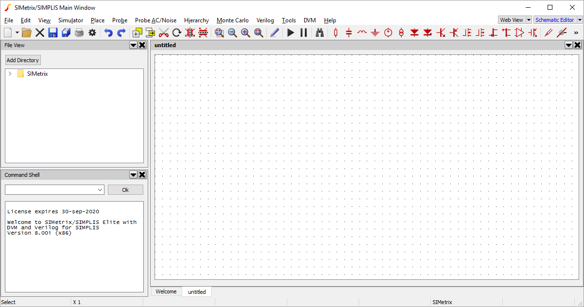
From any window, go to the menu at the top of the window and select: . The window will display a new schematic panel, similar to that below:
Placing Components
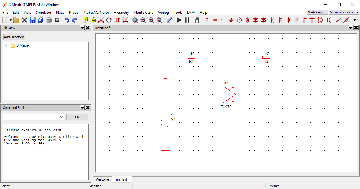
For this tutorial, we will create a simple non-inverting amplifier. To start, we'll place the components that we require: a voltage source as input, two resistors, an op-amp and ground.
To place the first component, press the Place Voltage Source button  on the toolbar. Now when you move the cursor back onto the schematic, the outline of the voltage source component will appear. Left click on the schematic to place the component at that position.
If you move the mouse, you will notice that the outline of the voltage source is still attached to the cursor. This would allow you to place another instance of that component. In this tutorial we do not want a second voltage source, so right click on the schematic to end component placement. The cursor will now return to normal.
Next we will place two resistors. Like last time, press the Resistor button  , but unlike last time, before placing the element we are going to rotate it 90 degrees. To rotate the element, move the cursor back onto the schematic so the resistor outline appears, then press F5. The resistor should rotate 90 degrees clockwise. Now left click and place a resistor, then move the mouse to another part of the schematic and left click to place a second resistor. When both resistors are placed, right click to end component placement.
 on the toolbar.
Finally add two ground components  and an op-amp component
  using the same method as we have for the voltage source and resistors. At the moment we are not worried about their position and the components can be placed anywhere on the schematic.
After components have been placed on the schematic they can be moved by left clicking on the component, then dragging it to the new location. Multiple components can be selected by left clicking on the first component, then press and hold the control key and click on the other components to move together. When all components have been selected, release the control key and click-on then drag any of the selected components. Selected components by default have a blue colour.
Arrange the components on the schematic so that they are laid out roughly in the same way as shown below.
Placing Wires
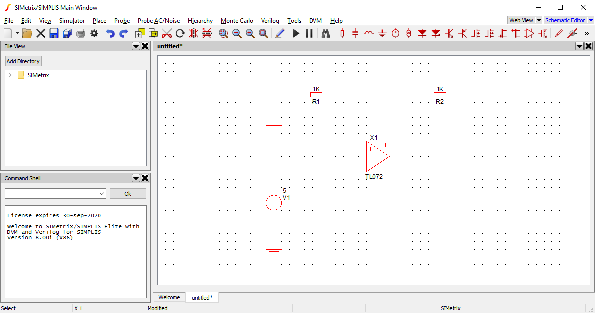
Next we will add wires to connect the components. SIMetrix provides a Smart Wiring facility that makes placing wires faster and easier, by simply specifying the points that the wire should attach to.
To begin, move the cursor to the left-hand pin on the left most resistor (R1 in our example picture above). The cursor will change from a cross-hair to a pencil. Left-click on the pin and will notice when you move the cursor that a straight line will be drawn from the pin to the cursor.
Now move the cursor to the pin on the nearest ground component and click on the pin. A wire will be added that automatically connects the two pins. Your schematic should now look like the one below.
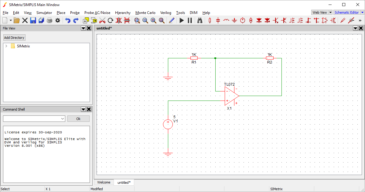
Next we will connect the positive output of the voltage source to the positive input of the op-amp. We could do this as before, however we would end up with wires crossing near the op-amp when we later connect the left resistor to the negative input. Ideally we then want the op-amp to be flipped horizontally so that the input pins are the opposite way around.
To flip the component, left-click on the op-amp (ensuring it is the only component selected) and press the Flip button  on the toolbar. The component should now flip over with the positive and negative sides reversed. The component will also appear a little higher that it was before the flip, so move it back down and then connect the voltage source positive output and op-amp positive input.
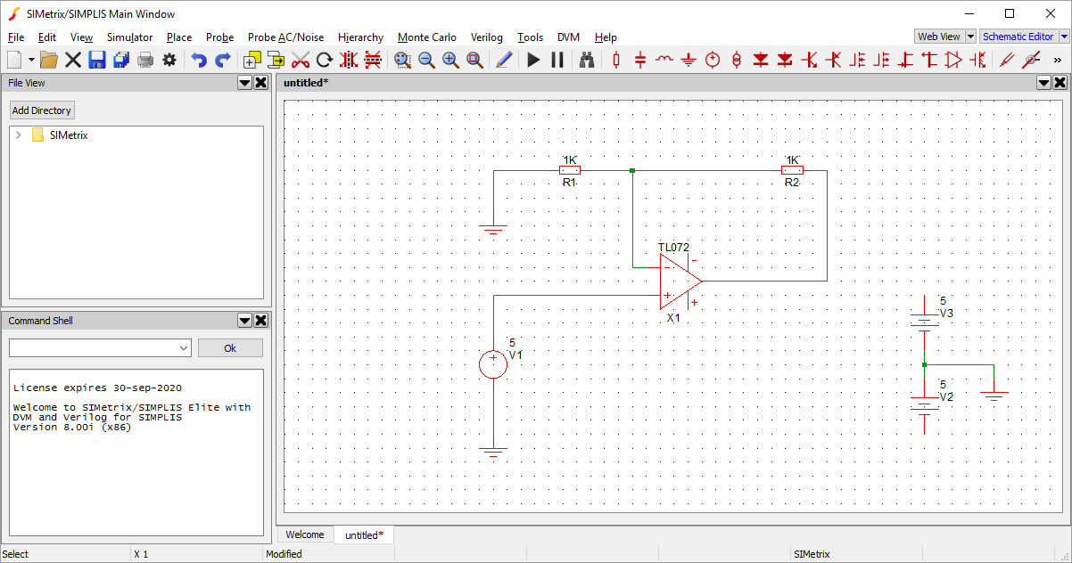
Continue to wire all connections, so that the non-inverting amplifier looks like the image below. If you need to move wires, you can click and drag them as you do for components. Attached wires will attempt to resize with the movement.
Connectors
Next we will add our supply rail to the op-amp. To keep our design clean, instead of routing wires from the power supply directly to the op-amp, we will use connectors.
We will start by building a power supply that runs between + and - 5V. To create the power supply, use the menu then place two power supply comnponents vertically next to each other.
Next add a ground component and connect all three together as shown in the picture below.
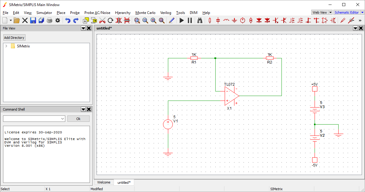
By default, the power supplies generate 5V, so we now have our +5V and -5V outputs.
Next we will add two connectors, one of the +5V source and the other for -5V. Connectors with the same name are all directly attached, as such the ground component is a commonly used case of the connector component, which by default has it's own symbol.
To add a connector, go to the menu , then place connectors above and below the power supply, rotating the connectors as required.
By default all connectors connect to VOUT. We will need to change the name of the connectors so we have our +5V and -5V connections.
To change the name of the connector, double click on one of the connector elements. A pop-up box will appear asking you to enter text, with a default value of VOUT. Change the text to +5V or -5V, depending on which connector you have double clicked, then press ok. You will notice the label displayed above or below the connector will have changed. Repeat this renaming step for the other connector. Your schematic should then look like the one below.
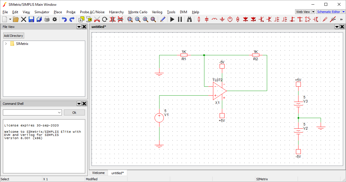
Now we need to add matching connectors to the supply rail of the op-amp. First select the +5V connector by clicking on it, then press the duplicate button  (or the default shortcut Control-D). The cursor will show the outline of a connector, move and rotate it as required to place it next to the +ve supply rail of the op-amp. Repeat this for the -ve supply and wire the new connectors to the supply rail pins on the op-amp.
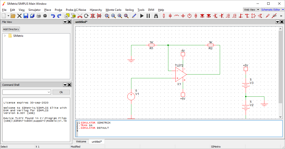
Your completed schematic should look like this.
Running a Simulation
With the schematic laid out, we can now run our first simulation. To simulate our schematic, first we must choose the type of analysis that we want to perform.
Go to the menu . The window below will pop-up.
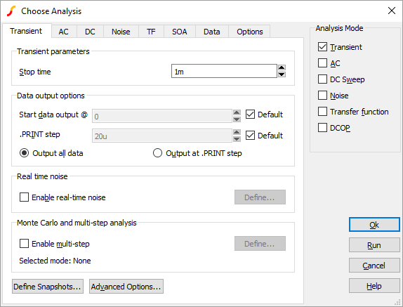
If the window you see looks different to the one displayed here and the title of the window has the word SIMPLIS in it, then you are using the wrong simulator. In this case, simply close the analysis box and select menu . Then re-open the Choose Analysis window and the one shown above should appear.
We want to run a transient simulation, so check the Transient box on the right hand side of the window, under Analysis Mode. When this is done, press the Run button in the bottom right of the window.
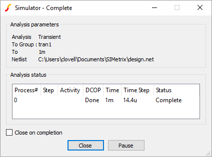
The Choose Analysis window will disappear and a Simulator window will open. If everything worked as expected, it should give a status of complete and look like the one below.
Visibly this dialog is the only immediate output of the simulation, based on how we have set up our circuit. A netlist has been generated, which we can view by clicking back on the schematic and then pressing F11. A text box will appear below the schematic, like the one shown below. Pressing F11 again will make text box disappear.
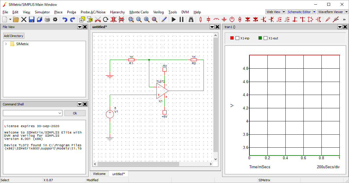
We can probe the voltage within the circuit by using the menu . The cursor will change to an icon of a voltage probe. You can then click on a wire to inspect the voltage, the waveform viewer will automatically appear in a new panel next to the schematic. In the following picture, the wire connecting the output of the voltage source to the op-amp and the wire connected to the output of the op-amp have been probed.
This is clearly a fairly boring simulation that has been run, as the input voltage has remained constant throughout. So we will need to adjust the parameters on the voltage source.
To adjust the properties, double click the voltage source component, the following window will pop-up (note the Pulse tab will be selected by default).
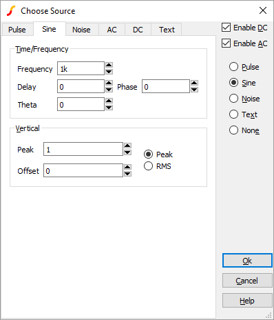
Tick the Enable AC check box and select the Sine option on the right hand side of the dialog, then press Ok. The label next to the voltage source will change to reflect the adjustments we have made to the component.
Before we re-run the simulation, we will make the process of checking the voltages a little quicker, by placing fixed probes to the schematic, instead of having to perform a manual probe after each simulation.
To place the fixed probes, go to menu (or use keyboard shortcut B), and place the probes like we did for the previous components, one on the wire connecting the voltage source and the op-amp and the other on the wire connected to the op-amp output.
Close the waveform viewer panel, so we get rid of our previous result, by pressing the cross in the title bar for the waveform panel.
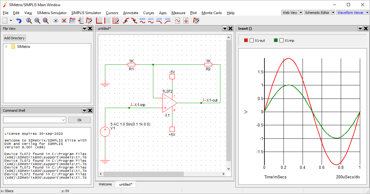
Finally, re-run the simulation by pressing the run toolbar button  or by clicking on the schematic and pressing F9. The final output should look similar to that shown below.
Next Steps
Now that we have successfully run a simulation, we can advance on to learn more about the SIMetrix and SIMetrix/SIMPLIS program.
Tutorial 3: Using the Waveform Viewer