Tutorial 1: Getting Started
This tutorial will help familiarise yourself with the SIMetrix front-end.
To begin you will need to instal SIMetrix, SIMetrix/SIMPLIS or our free demonstration program SIMetrix/SIMPLIS Elements. This tutorial is designed for version 8 and beyond of SIMetrix and SIMetrix/SIMPLIS, and all versions of SIMetrix/SIMPLIS Elements.
Download SIMetrix and SIMetrix/SIMPLIS Full Version
Download SIMetrix/SIMPLIS Elements
Learning the Interface
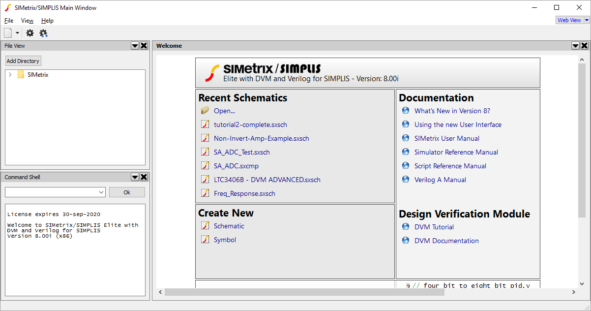
When you start the program, a single window will appear you will be presented with the welcome page, similar to the one below. Depending on your product and version this welcome page will appear differently. From this page you can perform common first actions, such as opening recent files, viewing the documentation and creating new schematics.
The default settings will also provide panels showing the File Viewer and Command Shell (the Command Shell is not available in SIMetrix/SIMPLIS Elements). The File Viewer displays the content of the SIMetrix directory in your Documents folder and can be used to quickly access all associated files such as schematics and scripts. The Command Shell allows for advanced interaction with the application, giving access to the scripting system.
View Panels
All panels within SIMetrix and SIMetrix/SIMPLIS can be relocated, resized, moved to another window, or closed completely. Note, there are some restrictions to these actions in SIMetrix/SIMPLIS Elements.
To move panels around, simply click and drag the darker grey title bar at the top of each panel. A blue outline will show you where the panels can be placed. At the moment the placement options may be fairly limited as we have only a small number of panels visible. When working with a larger number of schematics or waveforms, this behaviour becomes more useful, so you can view content side by side, or in any layout you require.
Each panel has its own context menu that provides options to move or close the panel. This context menu can be opened by pressing the down arrow button on the menu, as shown below, or by right clicking on the menu.

Panels are split into two categories: System Panels and Workspace Panels. System Panels provide methods to operate the program, such as the file viewer and command shell. Workspace Panels provide methods of using the program to create content and review designs, for instance with the schematic editor and waveform viewer. In using the panels, the only differences that occur are that System Panels will always appear on the outside edge of a window, whilst Workspace Panels will appear in the center or main part of the window. Additionally, Workspace Panels have a menu bar and toolbar associated to them.
Menu Bar and Toolbar
The menu bar and toolbar that appears at the top of the window is dependent on the Workspace Panel that is currently selected. Below are examples of the menu bar and toolbars that appear for the welcome page and a schematic.


You can tell what Workspace Panel is selected, by looking at the title bars of the panels in the window. Each title bar contains the name of the panel, in the selected Workspace Panel, this title will be in bold. You can swap between panels by either clicking within them or on the title bar. You will notice that the System Panels never have bold titles, as they cannot be selected for displaying a menu bar or toolbar.
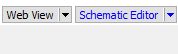
A second way of determining the type of Workspace Panel the toolbar is being displayed for is to look at the buttons on the top right of the menu bar and toolbar block. As you can see in the picture below, one of the them is highlighted blue, this is the type of workspace panel that is selected. These buttons can also be used to quickly swap between workspace panels. Clicking on the button will display the last viewed panel of that type in this window. Pressing the arrow will bring up a menu allowing you to quickly move all panels of this type to a new window, or close all panels of this type.
Next Steps
In the following tutorial, we will create our first schematic and perform a simulation.
Tutorial 2: Creating a Schematic and Running a Simulation