Installing Models
| Versions | 5.3 to latest version |
| Products | All products |
| Released | 21 November 2006 |
Summary
SIMetrix is able to import simulation models from many sources. In particular, most device manufacturers provide SPICE Models for their components and the vast majority of these are compatible with SIMetrix.
This article describes the procedure required to install models and also some of the problems that are commonly experienced with models.
Note that this article does not cover the installation of models from process foundries used for integrated circuit design. For this, see Using Models from Process Foundries.
What is a Model File
Simulation models consist of a number of lines of text providing a definition of the electrical characteristics of the device. The lines will reside in a file which may also contain other models. Often however, the file will contain just one device model. Typically the files have the extension .CIR, .MOD, .SPI or .LIB, but this is by no means always the case. Note that SIMetrix doesn't care what the file extension is.
Model files will always have either lines beginning .SUBCKT or lines beginning .MODEL and quite commonly you will see both. If there are no lines that start with either of these two words, then the file is not a SPICE model file and will not be useable by SIMetrix.
Obtaining Model Files
The exact procedure for obtaining the model file varies from one manufacturer to another. Commonly, manufacturers provide a link to SPICE Models on their data sheet page.
Unfortunately, its difficult to give detailed instructions on exactly what you do with this link as this varies between sites - and sometimes between different pages on the same site. But the following are, we hope, useful guidelines.
On most sites, you should not click on the link directly, but instead "Save Target As..." (right click pop up menu in Internet Explorer) and select a suitable location to save to on your hard disk. A default file name will usually appear and if this has the extension .MOD, .CIR, .SPI or .LIB, then you can be reasonably confident that you are saving a correctly formatted model. (These aren't the only file extensions used - they are just the most common. )
If the file has the extension .HTML or .HTM then you shouldn't save it, but cancel and then click on the link in the normal way. You will then be directed to a new web page which may have more links on it. In the case of Analog Devices, for example, you will be presented with a legal agreement that you have to agree to first. When you press the "I agree" button, the browser is then directed to display the text of the model. In this case you should now save the page that is displayed. But, and this is important, you must save the page as plain text. The default with Internet Explorer is to save as an HTML file and this will not work as a model. To save as plain text in IE, select "Text file (*.txt)" in the "Save as type" drop down box. You will get a file with the extension .TXT, but that's OK, SIMetrix will handle it. (But you may prefer to change it to some more suitable extension.)
The end result that you want is a text file that contains lines starting with things like ".SUBCKT", ".MODEL" and ".ENDS". It should definitely NOT contain lines containing <HTML>, <HEAD>, <META .... >. The latter are HTML tags and if your file has these in it then it means that it has been saved as web page. You should instead save it as text file - see above.
Installing the Model in SIMetrix
With SIMetrix, all you need to do to install a model is pick up the model file or model files or directory containing model files and drop them in the SIMetrix command shell. That is all you need to do to install the electrical model itself. It may not be all you need to do to use the model in the schematic editor, but we will cover that issue later.
Here is the drag and drop procedure in detail:
- Start SIMetrix if you haven't already. Make sure the command shell window is clearly visible.
- In Windows, navigate to the folder with your saved SPICE model file
- Drag and drop the file onto the SIMetrix command shell window.
- You will now see a message asking you to confirm that you would like to install the file. Select OK.
That is all that is needed to install the electrical model. You may also need to provide some further information to use the model in the schematic editor. This is explained in the next section.
Placing the Device on a Schematic for the First Time
Once you have installed the electrical model, you should be able to see it listed in the schematic's parts browser. This is what you do:
- Open a schematic sheet
- Select menu Place | From Model Library...
- On the left hand side, select the * Recently Added Models * category
- You should see the part numbers of the models you installed on the right hand side. If you don't see the models you installed, see Troubleshooting and Common Problems
- Select a part that you would like to place
- You may see the symbol for the model in the preview window on the bottom left. If the part is unknown to SIMetrix, you will see the message "SIMetrix does not know what symbol to use for this model...". In either case, press Place
If presented with a symbol, all you need to do now is place it and carry on with your schematic design. You can skip the remaining steps.
If SIMetrix is not able to figure out what the model is, you will now be presented with a dialog box like the one shown in step 9 below.
- You now need to supply two pieces of information: the part category (e.g. NMOS, Op-amp etc) and a suitable schematic symbol. For the category, select Choose Category for ??? where ??? is your part number (SXOA1000 in the example below). Select a suitable category or create a new one by pressing New Category...
Now select a suitable symbol from Define Symbol for ???. If there is no suitable symbol available, press Auto Create Symbol to create a new one. The new symbol will be functionally correct although it may not be ideal. You can change the pin names if these are not suitable by pressing Edit Pin Names... and you can edit the symbol graphics after the symbol is placed on the schematic.
You will now see something like the following:
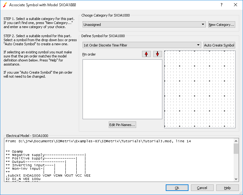
- If you selected an existing symbol in 9. above, you should now check the pin order. The box labelled Pin order shows the names of the symbol's pins. The order of these pins must match the order of the equivalent connections in the electrical model. Usually, the electrical model contains comment lines that describe each connection and the above example is typical. In the above example, the first connection is called 'VINP' and is the 'Non-inv input'. The second is 'VINN' and is the 'Inverting input' and so on. These correspond to the symbol pins 'inp' and 'inn' respectively.
However, in the example, the remaining three connections do not match the symbol's pins. The connection 'VOUT' should map to the pin 'out', but as it stands it maps to 'vsp' (positive supply). So we need to change the pin order. To do this, select the pin you wish to change then use the up and down arrow buttons on the right to move it. We only need to move the 'out' pin in the above example so that the order reads 'inp', 'inn', 'out', 'vsp', 'vsn'.
You do not need to check or change the pin order if you used Auto Create Symbol to create the symbol - Press Ok. You will be presented with the selected symbol to place on the schematic.
You will not need to repeat the above association procedure when placing the same device again. SIMetrix stores this information permanently.
Troubleshooting and Common Problems
Model seemed to install OK, but cannot find part listed
- Check that you are looking for the right part. The part name listed will be the name given in the model definition, not its file name. To find this out, you will need to open the model file in a text editor such as notepad. The part's name is the name immediately after its ".SUBCKT" or ".MODEL" line.
- If you can't find the part in '* Recently Added Models *' try looking in '* All User Models *' instead .
- Check the file you installed is a valid SPICE model. Open the file in a text editor and look for lines beginning .SUBCKT or .MODEL. If no such lines exist then the file is not a valid model file. Also every .SUBCKT line must have a matching .ENDS line. There exist models in the public domain where the .ENDS line has either been missed completely or instead a .END line is used. Neither is valid.
.SUBCKT and .MODEL must start the line. If other words or character sequences preceed it then the line will be ignored. This happens if the file is saved as HTML - you will see things like <HTML> and <HEAD> at the start of the line. - Check that the file uses ASCII coding and not UNICODE or other. To check, open the file in notepad, then select File | Save As... . If the Encoding box says anything other than "ANSI", then select ANSI and save. Then select SIMetrix menu File | Model Library | Re-build Catalog - this will tell SIMetrix to rescan the file.
- The model name might be clashing with an existing model. If there are duplicate model names, only the first one found in the search will be available. To find if there is a duplicate, select Place | From Model Library... then select the * All Devices * category. Type the expected model name in the Filter box and press Apply. If the device is listed, select it. You should see the file location of the model displayed at the bottom of the window. If this isn't the device you installed, then you should rename your model. Note that you must rename the name within the file, not the file itself. To do this, open the file in a text editor and change the name immediately after the .SUBCKT or .MODEL keyword. We suggest you append some suitable suffix e.g. a '-' followed by your initials or maybe an acronym of the manufacturer's name. When you have renamed the model, select menu File | Model Library | Re-build Catalog.
Successfully installed and associated model, but it doesn't work
- Check the pin order. You can do this with the associate models dialog box. Open the box (File | Model Library | Associate Models and Symbols...) then under Select Devices select the category which you gave the part. (Op-amps in our example). Locate the part in the list below.
Now carefully check the pin order against the electrical model. You might like to open the symbol in the symbol editor so that you can see which pin is which..
You can remap the pins using the up and down arrow buttons. When complete, press Apply Changes then close box. Note that this process will not update any existing symbols already placed on a schematic. You must delete these and re-enter using the Place | From Model Library... menu - The symbol you are using does not have a REF property. If you manually created a new symbol for the model, you should use the symbol editor's Property/Pin | Add Standard Properties... menu to add the standard properties needed for simulation symbols.
- Did you place the device using the Place | From Model Library... menu? If you used the alternative Place | From Symbol Library... to place, for example, a new symbol that you created, it might not work as it may not have the correct properties assigned. Place | From Model Library... automatically adds the necessary properties (except REF - see 2. above)
Cannot find a suitable symbol for association
- The associate models dialog box will only list symbols with the correct number of pins. So if the model is a 5 terminal opamp, then only symbols with 5 pins will be listed. But there are a very small number of erroneous models in existence that have additional text at the end of the .SUBCKT line that SIMetrix thinks are additional connections. Here is an example taken from a real model:
.SUBCKT LF347 1 3 2 4 5 (analog)
The "(analog)" on the end of this line should not be there. The designers probably meant it as a comment, but nearly all SPICE based simulators including SIMetrix will treat it as an additional connection. The best solution here is to edit the model and remove the extra text. - Use the Auto Create Symbol feature to create a new symbol
When I dropped the file into the command shell I got the message 'Unknown file type'
- This can happen if the file in in Apple MAC format. UNIX, DOS/Windows and Apple MAC all use a different sequence of characters to represent a new line. SIMetrix is compatible with DOS/Windows and UNIX formats but not Apple MAC.
Otherwise the message means that the file is not a recognised SPICE model file. Note that this is not related to the file extension. SIMetrix opens the file and has a look inside to determine if it is a model file. It doesn't care what the file extension is. - To convert a MAC file to DOS/Windows, download this utility - u2d.exe - and run from a command prompt:
u2d filename
Replace filename with your model file.